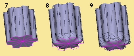
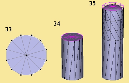
Change the Extrude Direction to Y and a Distance of 1. This will give us the central portion of the handle as shown in Pic 7 below.

 with shift and ctrl pressed (shift for a uniform scale,
ctrl for a centred scale) to shrink them toward the centre to give the result shown in Pic 2.
with shift and ctrl pressed (shift for a uniform scale,
ctrl for a centred scale) to shrink them toward the centre to give the result shown in Pic 2.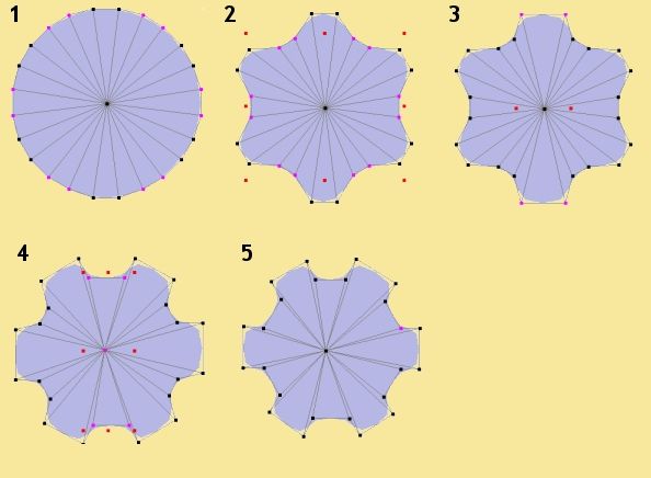
|
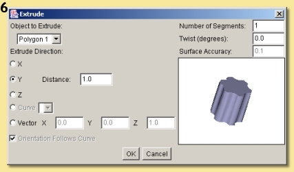
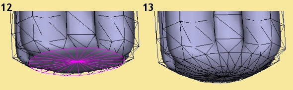
Now to make it 3D! We do this with the Extrude tool. Make sure the polygon is selected and go to
Tools -> Extrude. This will display a dialogue similar to that shown on the right: Change the Extrude Direction to Y and a Distance of 1. This will give us the central portion of the handle as shown in Pic 7 below. |
|
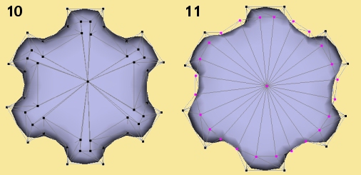
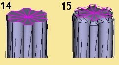
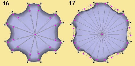
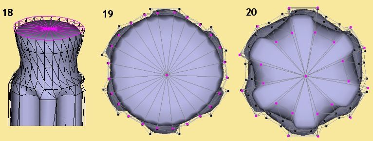
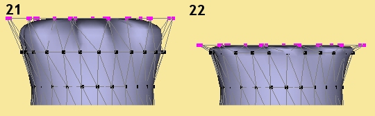
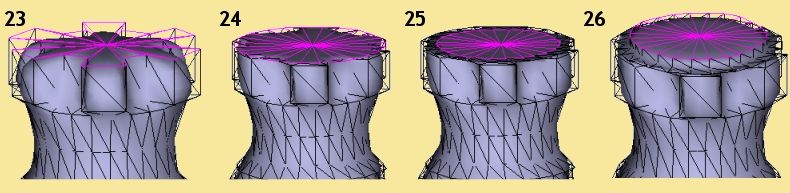
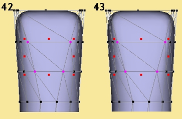
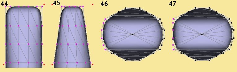
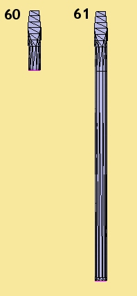
 and taper out the top by holding
Ctrl and dragging one of the top handles outwards slightly as shown in Pic 37. Now
select the points shown in Pic 38 i.e. one in from the last selection (front and back),
and repeat the taper
operation to get the result shown in Pic 39. Select the central columns of points
shown in Pic 40 (front and back) and taper those to get Pic 41.
and taper out the top by holding
Ctrl and dragging one of the top handles outwards slightly as shown in Pic 37. Now
select the points shown in Pic 38 i.e. one in from the last selection (front and back),
and repeat the taper
operation to get the result shown in Pic 39. Select the central columns of points
shown in Pic 40 (front and back) and taper those to get Pic 41. 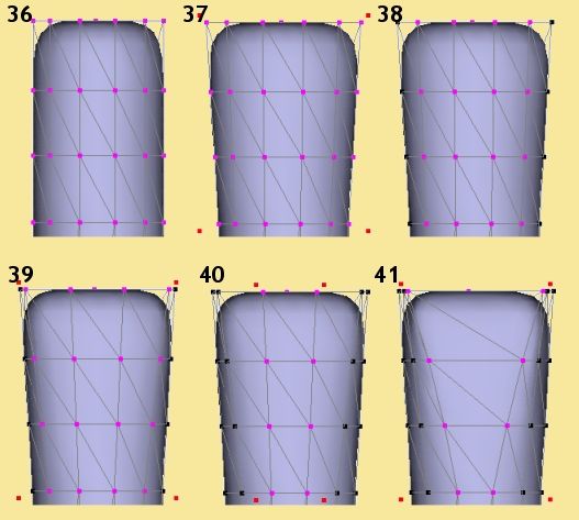

|
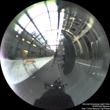
Click on Insert -> Patterns -> Image to add an Image module to the editor's 'canvas'. Now
double-click on the module to bring up a dialogue in which you can set the image (as well as its
tiling and mirroring). Click on the blank square at the top to display thumbnails of images already
in the scene - or not, as you shouldn't have yet. Click on 'Load' and select the HDR image - this
should now be displayed on the thumbnail list. Click Done and the image should now appear
in the previously blank image box in the Set Image dialogue. Now click OK to return to the
procedure editor where the image should now be displayed in the image module as shown on the right. |
 |
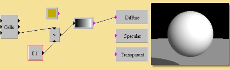
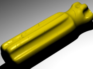
So to start
insert a Color module (Insert -> Values -> Color), double-click on it to open a colour
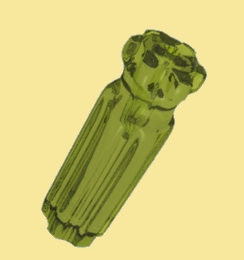
chooser dialogue and create a yellowish colour like  . The handle is
also going to be reflective, so later we're going to use the Specularity parameter but for now we'll
just use the Shininess property. This property is actually a cheat to simulate the reflection you
would get on a surface from a light source - if you're using standard light sources in a scene, you
will need Shininess as well as Specularity (which is true reflection of the surroundings) because
light sources are not visible and therefore are not reflected. When using a HDR image, this image
usually contains the lights as part of the image and so they will be reflected in a surface with
specularity. So, later on we will switch from using Shininess to using only Specularity. But, for now,
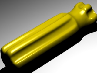
create a Number module and plug its output into the Shininess box. Double-click the Number module and
enter a value of 0.8. Click OK to accept the texture and assign the texture to the handle (click right
on the handle in the Object List and select Set Texture, choose the texture and click OK). . The handle is
also going to be reflective, so later we're going to use the Specularity parameter but for now we'll
just use the Shininess property. This property is actually a cheat to simulate the reflection you
would get on a surface from a light source - if you're using standard light sources in a scene, you
will need Shininess as well as Specularity (which is true reflection of the surroundings) because
light sources are not visible and therefore are not reflected. When using a HDR image, this image
usually contains the lights as part of the image and so they will be reflected in a surface with
specularity. So, later on we will switch from using Shininess to using only Specularity. But, for now,
create a Number module and plug its output into the Shininess box. Double-click the Number module and
enter a value of 0.8. Click OK to accept the texture and assign the texture to the handle (click right
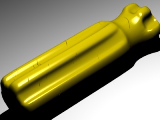
on the handle in the Object List and select Set Texture, choose the texture and click OK).You should get the result on the right: This is fine as a basic hard yellow plastic. |
 |
|
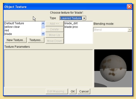
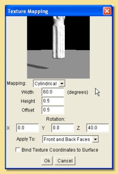
See the manual for a full description of what everything does. Basically we have 3 choices for wrapping
the texture around the object; Projection, Cylindrical, Spherical.
Because the shape of the screwdriver
is essentially cylindrical, select that Cylindrical. You will then need to play around with the
scaling and
the position of the texture to get the scratches in the right place. The Width and Height fields vary the scaling of the texture and the Offset moves it around. It can also be rotated by entering appropriate values lower down. Use the values in the image on the right or derive your own and click OK to set the texture. |
 |
|
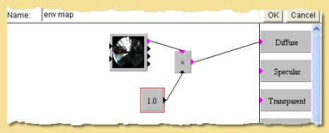
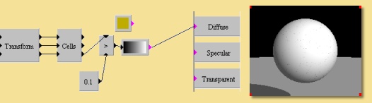
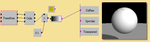
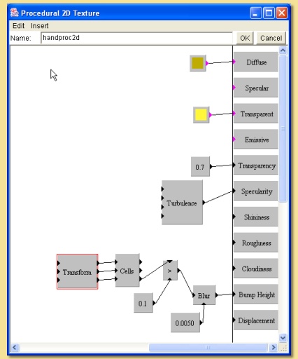
Now to make it transparent. Re-enter the procedure editor. We're simply going to set a constant value
for the transparency property. Insert a Number module and set it to 0.7 and plug the output into the
Transparency box. That makes it uniformly transparent but we also need to set the Transparent Color correctly - when light passes through the clear plastic it will pick up a yellow tint so add a Color module to the canvas, set it to a light yellow and plug it into the Transparent Color box. While we're at it, delete the connection between the Turbulence module and the Shininess box and plug it into the Specularity box for the full effect. The final texture is shown on the right and a test render should look like this: |
 |
|
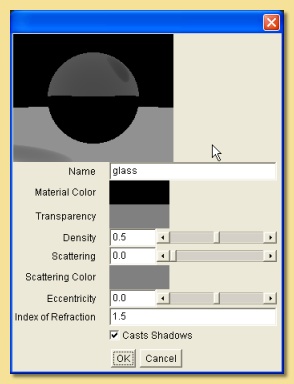
See the manual for more details of all the settings. We're actually going to leave them all as they are
except the Index of Refraction which will give us our distortion. Change this to about 1.5 for a
hard plastic or glass material. Set the material to the handle by right clicking on the handle on the Object List and selecting Set Material. Select the material and click OK. A final render should look like that below - that's the handle finished: 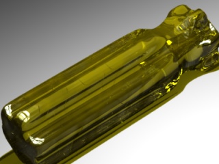
|
 |
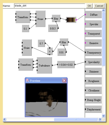
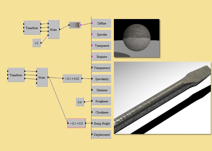
| The first thing we'll do is create the Diffuse colour - insert a colour map (Insert -> Color Functions -> Custom) and double-click it to open the colour map editor. Click on the small arrow on the left of the colourbar to display the colour at that part of the map on the small rectangle identified as Color. To change this colour, click on the rectangle - this will open the colour chooser dialogue. I want to have a basic metallic grey here e.g. Hue-0.0, Saturation-0.0, Value-0.63. Click OK and then select the small arrow at the other end of the colourmap - set this colour to a dirty brown e.g. H-0.09, S-0.37, V-0.43. This gives a map which is a linear change between the 2 colours. However, I want a more sudden change between grey and brown so add another colour to the map by clicking Add. This will add a new small arrow at the centre of the map - click on it and change the colour to the same grey as we set for the left side of the map (see right). Click OK and connect the output to the Diffuse box. | 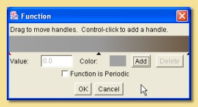 |
| You should now see some brown appear on the preview. At this stage the brown is a bit too wishy-washy. To improve this, increase the noise in the pattern by adding a Number module, setting it to 1.0 and plugging it into the noise input (the bottom input) of the Noise module. Finally reduce the scale of the pattern by adding a Linear Transform module, setting the X, Y and Z scales to 10.0 and connecting all 3 inputs to the Noise module as shown on the right: | 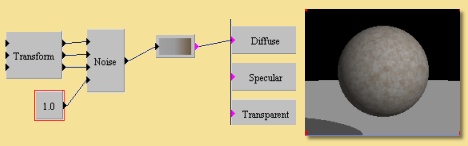 |
|
Now let's add some specularity to the metal. First off, just try setting a constant specularity by
inserting a Number module, setting it to 0.5 and connecting it to the Specularity box. We also want the
surface to be rough so that specular highlights are spread out and reflections are blurred - to
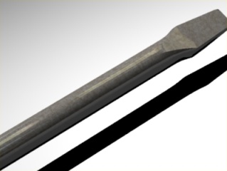
achieve this, add a Number module, set to 0.6 and plug it into the Roughness property box. Assign the texture to the screwdriver blade and use the Edit Mapping dialogue to get the right scale for the pattern. Due to the long, thin nature of the object, it will difficult to assess this in the Edit Mapping preview so you will need to do a series of test renders to get it right. I set the X,Y and Z scaling to 0.2 to get the result on the right: |
 |
|
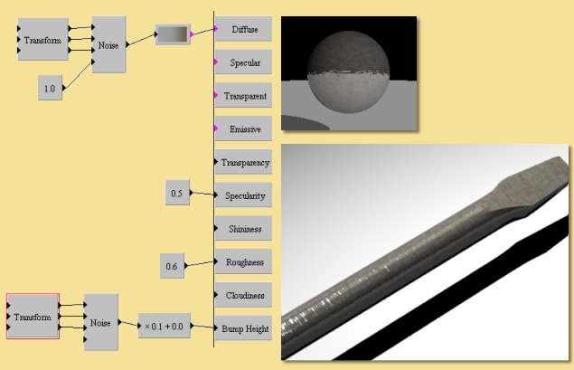
Now we're going to add some anisotropy to the texture to get the brushed metal look. We'll do this
is 2 ways; first by creating some fine stretched bumps. Add a Noise pattern module and plug it into the
Bump Height box. Reduce and stretch the scaling of the noise pattern by adding a Linear Transform module,
setting the its Scale to X:1, Y:20, Z:20, and plugging all 3 outputs into the 3 inputs of the Noise
pattern. This compresses the pattern along Y and Z but not X. At this stage the preview shows that the bumps are too great. To reduce them, create a Scale/Shift module (Insert -> Functions -> Scale/Shift), double-click it and set the 'x' box to 0.1. This reduces the bump height 10 times. Your texture should now look like that on the right, with the test render also shown. Notice how it differs from the previous render, especially where the bumps catch the light from the HDR image. |
 |
|
To emphasise the anisotropy further, we're going to change from a uniform specularity to one that
varies in the same way that the bump map does. This is simply done; we're just going to take another
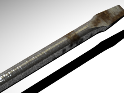
output from the Noise pattern we used for the Bump Height. First create another Scale/Shift module so that we can scale down the output (as this has an amplitude of 1 and this is too high). Plug the output of the Noise pattern into the Scale/Shift module, alter the values of the Scale/Shift to give 'x 0.5 + 0.05' and connect the output into the Specularity box in place of the 0.5 we had from before. This Scale value of 0.5 means that the specularity will vary between 0 and 0.5 depending on the value of the Noise pattern at a particular point on the surface. The Shift value of 0.05 will mean that all parts of the surface will have some reflection, even if the Noise pattern is zero there. The final base texture is shown on the right, together with a test render. You can see that we have a nice battered, scratched metal texture. |
 |
|
So, create a new procedural 3D texture. The first thing to do is get the diffuse colour looking right.
Create a custom colour module and double-click to edit the colours in the map. The colour map on the right shows the colours I used. Connect the output of the Custom module into the Diffuse box. |
 |
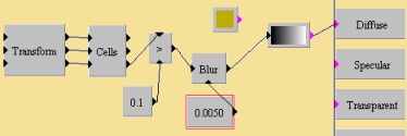
| Now, we're going to use a Noise pattern module as the basis of the colour pattern. So, create a Noise module and connect it to the input of the Custom color module. I wanted it to vary quite a bit so I increased the Amplitude of the Noise module to 2.0 (double- click the Noise module to alter it). Set the Octaves to 3.0. We want a small scale noise pattern so insert a Linear Transform module and connect it to the input of the Noise pattern. Alter the scaling of the Transform module to X:20, Y:20, Z:20. Just to smooth the noise slightly, add a Number module to plug into the noise input of the Noise module and set it to 0.1. To further smooth the pattern, add a Blur module (Insert -> Functions -> Blur), disconnect the link between the Noise pattern and the colour map and connect the output of the Noise to the Blur instead, then the Blur to the colourmap - the Blur is a little too much so alter the blurring factor by adding a Number module set to 0.015 as the Blur input of the Blur pattern. | 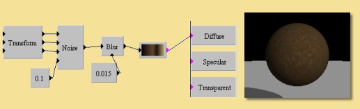 |
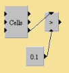
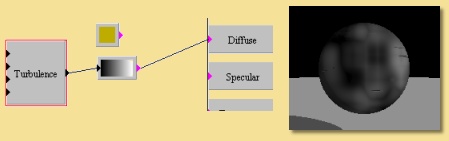
| Now, this texture is going to be applied as an overlay on the other blade texture we made. For this to work, we need to make some of this texture transparent so that the other texture will show through. We want this transparency to be a random pattern so we're going to use the Noise module again. So, create a Noise module with the default settings. To get this function to pick areas of the texture to make transparent in a reasonably discrete way, I have used the Greater Than function in a similar way as we did to get the scratches on the handle. This time we want areas where the Noise pattern is below a certain value to be set to 1 and everywhere else to be set to 0 - when connected to the Transparency box, this will create discrete transparent areas. So, insert a Greater Than module, plug the output of the Noise module into the bottom input and a Number module set to 0.7 into the top. If you try plugging the output of the Greater Than function into the Transparency, the 'discreteness' is a little too much, so use a Blur function between to soften it. | 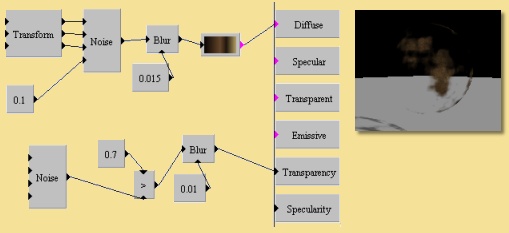 |