Prev: Transform Modules Next: The Properties Window
8. Pattern Modules
The modules in the "Patterns" category implement various patterns which are useful for creating
procedural textures. They all have inputs corresponding to the X, Y, and (in some cases) Z
coordinates of a point in space, and one or more outputs giving the values of the patterns at
that point.
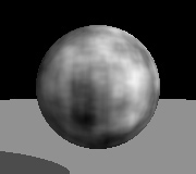
Noise
This module creates a fractal noise pattern by adding together several octaves of Ken Perlin's
simplex noise function. Each octave has twice the frequency of the previous octave. You can
specify the number of octaves to use, and the amplitude of the first octave. The amplitude
of each higher octave is obtained by multiplying the amplitude of the preceding octave by the value
of the noise input port (which is typically between 0 and 1, although this is not strictly
required). Because this is an input port rather than a parameter, it does
not need to be a constant. This is very useful for creating noise patterns whose character
varies over the surface of an object.
The noise function is scaled so that output values will typically be between 0 and 1. Depending
on the values of the parameters and the noise input, however, the output value may sometimes go
outside this range.
Turbulence
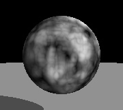
This module is like the Noise module, except that it takes the absolute value of each octave of
noise before adding them together. This creates "creases" in the output where its derivative
changes discontinuously. The result is somewhat reminiscent of turbulent flows in liquids.
The noise function is scaled so that output values will typically be between 0 and 1. Depending
on the values of the parameters and the noise input, however, the output value may sometimes be
greater than 1.
Grid
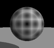
This module is useful for creating patterns that are based on a uniform grid. It defines a uniform,
three dimensional grid of "feature points". Given a point in space, this module outputs the
distance from that point to the nearest feature point. Double-click the module to change the
spacing between feature points.
Cells
This module implements Steven Worley's Cellular Texture Basis Function. This is similar to the
Grid function described above, except that the feature points are randomly scattered throughout
space, not arranged on a grid.
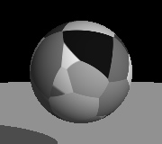
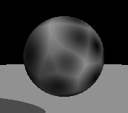
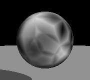
This module has three output ports. The cell port outputs a value between 0 and 1 which
identifies the nearest feature point. This value is the same for every point in the "cell" defined
by that feature point. This is useful for creating irregularly shaped cells, where each cell is
a different color. The distance 1 and distance 2 ports output the distance to the nearest
and second nearest feature points, respectively. Both of these patterns are useful for creating
a wide variety of procedural textures.
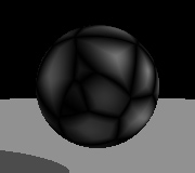
Another useful pattern is obtained by using a Subtract module to calculate
(distance 2)-(distance 1). This gives a pattern which is equal to 0 on the boundaries between
cells, and increases toward the center of each cell.
 |
 |
 |
 |
| Cell | Distance 1 | Distance 2 | (Distance 2)-(Distance 1) |
In all of the images shown above, the nearest feature point is determined based on Euclidean
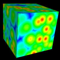
distance. The Cells module also offers a choice of two other distance metrics: City Block
distance and Chess Board distance. Each of these results in a distinctive pattern, which is
useful for different types of textures. Double-click the module to select which distance metric
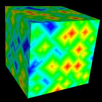
to use. In the images below, the cube is colored based on the distance 1 output of a
Cells module using each one of the three distance metrics.
 |
 |
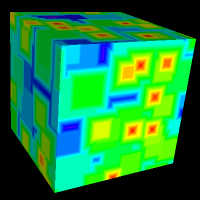 |
| Euclidean Distance | City Block Distance | Chess Board Distance |
| D = sqrt(dx*dx+dy*dy+dz*dz) | D = |dx|+|dy|+|dz| | D = max(|dy|, |dy|, |dz|) |
Marble
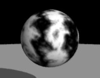
This module generates a pattern reminiscent of veined marble. It uses a sine function to
generate bands, which are perturbed with the turbulence function described above:
f(x,y,z) = sin(x+t(x,y,z))
This module has parameters for setting the spacing between bands, and the amplitude and number
of octaves for the turbulence function. The noise input corresponds to the noise input
of a Turbulence module.
Wood
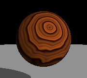
This module generates a pattern which is useful for generating wood textures. Its output for a
given point is proportional to the distance from the Y axis, plus a turbulence function. If you
select the "Only Output Fraction" option, the output is taken mod 1, so that it consists of a
series of concentric rings, with the output increasing from 0 to 1 over the width of each ring.
This module has parameters for setting the ring spacing, and the amplitude and number
of octaves for the turbulence function. The noise input corresponds to the noise input
of a Turbulence module.
The most common use of this module is to send its output into a Custom color function, which
creates an appropriate series of color bands. When used this way, it is generally best not
to select the "Only Output Fraction" option, and instead to make the color function periodic.
Otherwise, the anti-aliasing of the wood function may lead to visible artifacts.
Checker
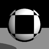
This module generates a checkerboard pattern, where its output is equal to either 0 or 1 in each
square. Actually, this is a three dimensional generalization of a checkerboard. Think of it as
stacked cubes, where the value of the function alternates between adjacent cubes.
Bricks
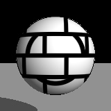
This module generates a brick pattern. This consists of bricks (in which the output equals 1) and
gaps between the bricks (in which the output equals 0). The bricks are stacked in layers, with
each layer offset from the layer below it. There are adjustable parameters for setting the height
of the bricks, the width of the gaps between bricks, and the offset between adjacent layers.
As with the Checker module, this is a three dimensional pattern. Cutting through it along either
the XY or YZ plane will yield a standard 2D brick pattern.
Image
This module allows you to use an image file (in any of the standard formats supported by Art of Illusion,
such as JPEG, PNG, or SVG) as part of a procedure.
There are five output ports. The first one is a color port which outputs the color of the image at
the specified point. The other four are number ports which output the values of the individual color
components.
Double-clicking the module brings up a window in which you can select the image to use, as well as
the following parameters:
- The size of the image. By default its larger dimension is set to 1.0, and the other dimension
is set to give the correct aspect ratio based on the shape of the image.
- Whether to tile the image in the X and/or Y dimensions. If you select these options, the
image will be infinitely repeated in either direction. If not, there will be only a single copy of
it positioned at (0, 0), and the outputs will equal 0 for points outside the image.
- Whether to mirror the image in the X and/or Y directions. If you select these options and
also tile the image, alternating copies of the image will be flipped relative to each other, which
guarantees that they will blend smoothly together at the edges.
- What set of color components to output from the 2nd, 3rd, and 4th outputs. Options are Red/Green/Blue,
Hue/Saturation/Value, or Hue/Lightness/Saturation.
Prev: Transform Modules Next: The Properties Window


