Creating a Simple Subdivision Human Character in Art of Illusion

by Julian MacDonald (feel free to email comments and suggestions)

Written: 6 July 2002 for Version 1.1

Updated: 18 August 2002


This is a tutorial showing how to use the subdivision surfaces available in the triangle mesh editor to create a simple humanoid figure.

Basic Model

Adding Hands


The Basic Model

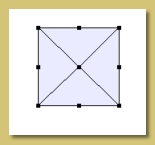
Let's start simply; create a cube and convert it to a triangle mesh (right click on object in Object List, choose Convert to Triangle Mesh and say 'OK' to verify the conversion). Now, double-click the mesh object to display the triangle mesh editor which should display the cube mesh as shown on the right:


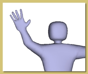
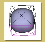
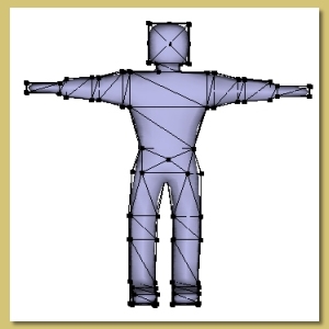
Now switch the display mode to smooth (View -> Display Mode ->Smooth) and switch on the 'approximating' subdivision mode (Mesh -> Smoothing Mode ->Approximating) to get 
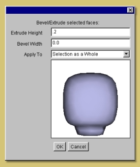
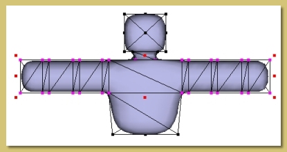
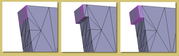
the mesh looking like that on the right. This is the head of the human model.

The basic method we're going to use to create our model is to extrude the various parts of the body out of the head. So, let's start with the neck. Select the 4 faces at the bottom of the cube as shown on the right and click on
Mesh-> Bevel/Extrude Faces to display the dialogue shown below.


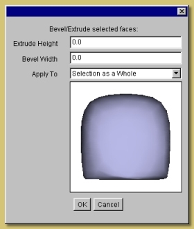
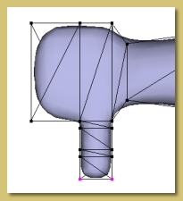
Keep the Extrude Height and Bevel Width at 0.0. You will see the preview showing a flattened base. Click OK to accept this and return to the mesh editor.

Now change the view to bottom and you will see the 5 points created by the extrude operation selected. Click on the scale tool and, while holding <shift> and <ctrl> (to make the operation both uniform and centred), click and drag one of the corner handles inwards to the dimensions of the neck as shown below:


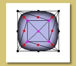
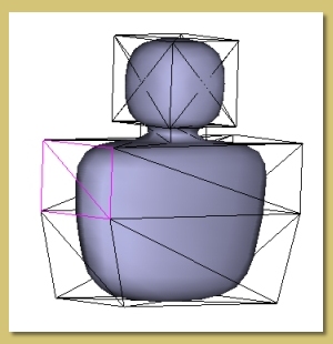
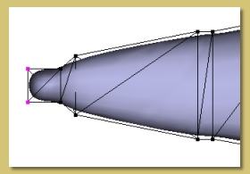
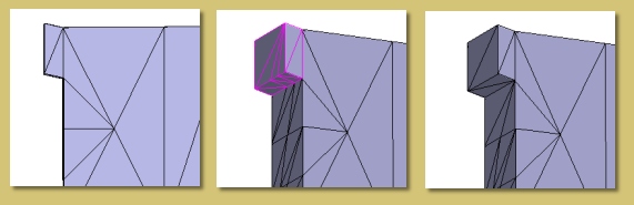
Now to create the rest of the neck. Switch back to face mode and extrude the currently selected faces in the same way as before but with an Extrude Height greater than 0.0. In the example on the right, I have used a height of 0.5 but this will depend on the scaling of your model. The height can be of course be adjusted later by just tweaking the points.

You can see the neck shape appear in the preview. Click OK to carry out the extrusion.

Now, extrude the selected faces again, this time with an Extrude Height of 0.0.


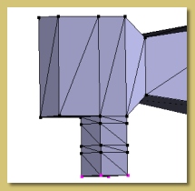
Switch to the bottom view again and use the scale tool to stretch the new points laterally to form the top of the shoulders. Also scale in the other dimension (i.e. vertically if looking at the bottom view) slightly. This should produce the result shown in the oblique front view on the right.


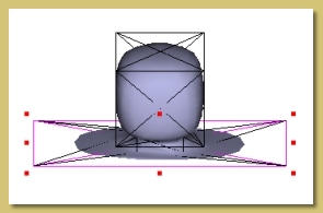
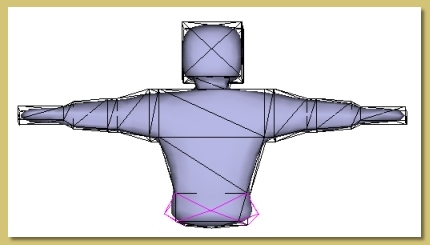
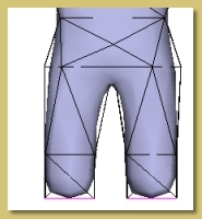
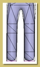
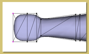
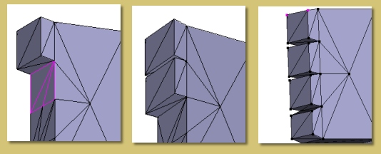
Now extrude twice more; the first time the Extrude height should be set so as to extend to just below where the arms are going to be. The second extrusion should be made larger to extend down to the waist. See the image on the right for reference.

Scale the points created by the second extrusion as shown to give a tapering at the waist.

Time to extrude the arms now. Select the 2 faces at each side of the shoulders as shown on the right.


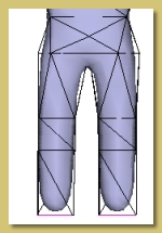
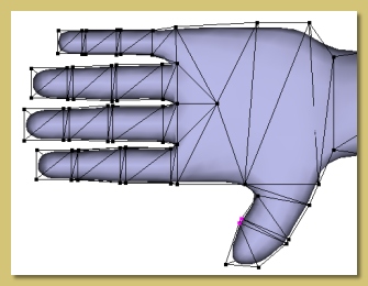
Extrude with a small Extrude Height initially for the shoulders, then extrude again with a longer Extrude Height for the upper arm, again with a smaller Extrude Height for the elbow, again with a longer height for the forearm, again with a small height for the wrist and, finally, with a longer Extrude Height for the hand.

Right, that's all the bits of the arm created; they just need scaling to the right proportions as shown below:


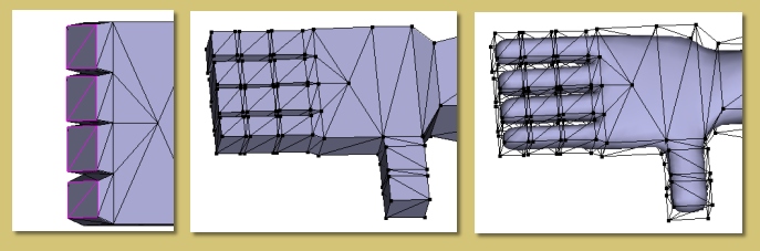
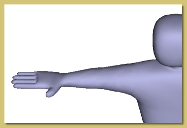
Switch to the top view and scale the various parts of the arm by selecting the relevant vertices and using the scale tool. This model has his palms parallel to the ground so that when we bend the arms down the hands wil rest realistically by his sides. Therefore, make the hands wide in this top view.


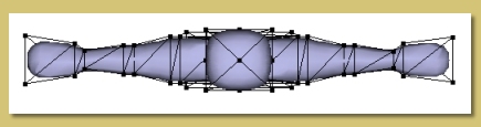
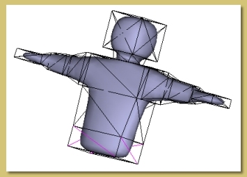
Having got the proportions right from the top, switch to the front view and adjust the scaling appropriately so that the figure looks similar to that on the right:

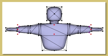
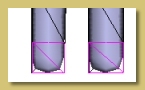
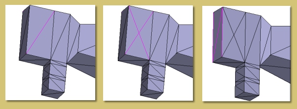
Now for the legs.

Now, to get a good smoothing effect with subdivision surfaces, I find it best to work with pairs of faces when extruding so that, in effect, we're working with quadrangles rather than triangles. That is what we have been doing so far. However, now we have a problem; we want to extrude 2 legs from the base of the body but we don't have 2 nice quadrangles to do it with. So, we're going to have to create them first using subdivision.

Here's one way: Select the bottom faces and extrude again with a smallish Extrude Height . Switch to edge mode and select the 4 diagonal edges created with the extrude operation as shown on the right.


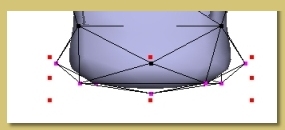
Now subdivide these edges (Mesh -> Subdivide Selected Edges) to create the new points shown on the right:

Looking at the underneath of the model, we can see there are 2 diamond quadrangles just waiting to be extruded (below):


First, however, we need to get the all the faces parallel to each other; extrusions are performed normally to selected faces so we need to make sure they all have the same normal. Select the faces, switch to point mode and front view (below left). Select the scale tool and drag the top middle handle down as far as it will go. This will flatten all the faces (below right).


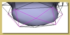
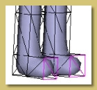
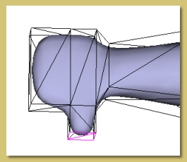
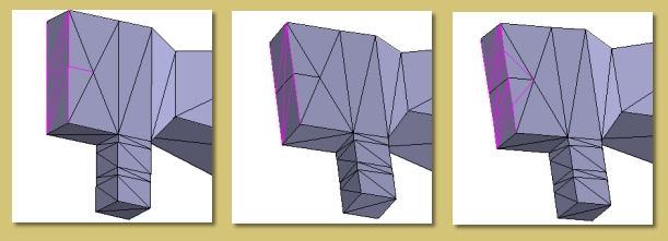
Now to extrude the legs; select the faces making up the 2 diamond quadrangles and extrude to produce the thighs as shown on the right.


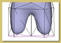
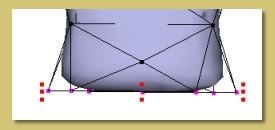
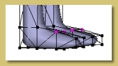
Now we're going to reorient the extruded faces so that they're more square-like and aligned with the body. Switch to bottom view as shown on the right and select the 4 points making up one of the diamonds. Use the rotate tool to orient them as shown, then the move tool to neaten up the 'square'. Repeat for the other side.
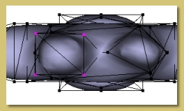

That's the tricky bit done. Now to carry on with the extrusions for the leg. Extrude a small way for the knees (below left), again for the shins (below middle) and again for the ankles (below right):


For the feet, select the faces at the front of the ankles (below left), extrude once for the main part of the foot (below middle) and once again for the toes. Scale the end of the foot to give a taper (below right).


Below is the final basic model.


Adding Hands


Below is a close-up of the forearm/hand. Move the vertices created in the last section back towards the wrist as shown.


Below is a top view. Select both the end faces and extrude again to get the palm shown.


Now we're going to create the thumb. Select the 2 faces together forming a quadrangle at the side of the palm near the wrist and extrude outwards to get the effect below:

Move these new points back towards the hand to give us plenty of vertices around the joint. Now extrude the new faces again 3 more times and move the points to give the other joint as shown.


Now for the fingers. The aim here is to extrude the fingers out from the end of the palm. Ideally, then, we want to split the faces here into 4 quandrangles from which we can extrude. Here's the trick; change the Smoothing Method to None to give the blocky appearance shown below. Don't worry; this is just temporary. Doing this changes the way subdivision works and will give us nice straight edges just where we want them. Here's how:


First, select the edge shown below left in the part of the palm just below where the fingers are going to start. Also select the edge in the same position on the other side of the hand. Select Mesh -> Subdivide Selected Edges to give the result shown below middle. The point of this was to create a symmetrical set of vertices/edges which gives a better result in the next stages.

Now to actually subdivide the end of the palm for the fingers. To cut this 'quandrangle' into 2 we need to subdivide all the edges that run across it. So select those 3 edges as shown below right:


Then subdivide the edges to give the result shown below left. Note that we have a nice straight cut across the 'quandrangle' which is just what we want. Had we carried out this operation with the approximating smoothing on, this wouldn't have been the case. Note also that we have actually got 3 faces making up each of the new 'quandrangle'. This is not what we want but we will sort this out later.

Now we want to split the new 'quadrangles' into 2 again. So, as before, select the edges that run across the 'quadrangles' (below middle) and subdivide them to give the result below right:


Now we have 4 nice 'quadrangles' as required. Unfortunately, the structure of faces making them up is a bit messy. Here's how to neaten them up:

First select all the faces making up one 'quandrangle' as shown below left. Extrude this a small way as 'selection as a whole' to give the result below middle. The idea is to select all the faces making up the finger base, as shown below right, and select Mesh -> Simplify Selection. However, here we hit a problem. If you try it you will find that other faces further into the palm are incorporated into the simplified mesh. This is because the finger base is perfectly aligned with the side of the palm and so the surface can be represented with a simpler form of the mesh and still maintain the same level of surface accuracy.


To get around this, move the extruded points laterally as shown below left in a top view. Then select all the faces in the finger base (tip: one quick way is to select the extruded points in Point mode, switch to Edit ->Tolerant Selection Mode , then enter Face mode) as shown below middle and select Mesh -> Simplify Selection . Accept the default Max Surface Error of 0.01 and, low and behold, we get a perfect mesh with only 2 faces for each 'quandrangle' as shown below right:


Select the next set of faces (below left), extrude and simplify as before (below middle). Repeat this process for the other 2 fingers to give the result shown below right:


Now to form the rest of the fingers. Select all the 'quadrangles' at the end of the fingers as seen below left. Extrude these several times by varying amounts to give the mesh shown below middle. As before, it is best to maintain a concentration of vertices around the joints. Switch the approximating smoothing back on to give the smoothed mesh below right.


We'ew almost there! Just alter the scaling of the fingers/thumb to give a more realistic shape and size to the digits as in the example below:


That's about it for now. Bye!